Building
Miss Conception by Morley S. Smith ( PART II )
| Miss Conception was designed
for the 1913 Harmsworth Trophy racing competition. When I found the hull
it was a half rotted derelict overgrown by brush out behind the machine
shop of Charlie Bowgus. Charlie was an old man and referred to the boat
as "Pop's Old Race Boat". I hauled the thing home and stored it in a corner
of my barn while I researched it's origin.
I wanted to take a set of
lines off the hull before I proceded to have a bonfire. The hull was turned
upside down on some braced saw horses, and I started to jack up different
points in order to get some sort of . alignment. The rotted hull was completely
flexible as there was very little decking and a major portion of the bottom
had rotted away on one side. The hull would take almost any shape I wanted
to put it in.
Eventually, I was able to
shim things until the engine stringers were relatively straight and the
keel sections were straight and parallel in profile. The shear line (the
line between the deck and the side panel 1 was higher (aboue the keel 1
at mid 1 ength than at the stem or the transom. What looked at first to
be a *broken back" condition, was apparently part of the original design.
The lines were drawn to a
distorted scale. Heights and widths are one quarter size and lengths are
to. one eighth size. This exagerates any curves in the hull lines and makes
errors stand out. A smooth set of lines was then drawn to eliminate the
variations which existed in the rotted prototype. A table of offsets, (dimensions
for the frames) wastaken from this drawing.
The more work I did on this
old hull, the more fascinated I became with it's peculiarities. M Y research
indicated that this boat was technically quite complex wi th it's combination
of stepped hull and surface piercing propeller. I can only find two instances
where such a combination has been tried since, and both have resulted in
very fast boats. The engineer in me wanted to build a replica, but I didn't
have much confidence that this odd shaped hull would really work. (I can
find no record that it ever was raced.) |
|
I built a model of the boat
and towed it back and forth across the South end of Lake Cayuga. With the
center of gravity aft where it would be with a short modern engine, the
model seemed to ride at a high angle of attack and ran very light on the
water. I built a second model with a sl ightly lower step and saw a distinct
improvement. This model had slightly more drag but was much smoother running,
so those are the proportions which I chose for the reconstruction. (The
step is 2 l/2" deep at the keel and 9 l/2" deep at the chine .
I took some liberties in the
layout of the reconstruction of this 1913 race boat. Since the new engine
takes up much less length than the original 8 l/2 motor bay, I lengthened
the forward deck and put a seat forward of the engine. I put a high cowling
ahead of the driver to try to deflect some of the wind. The cowling does
not extend the full width of the hull so that the riding mechanic is free
to walk around and service the engine. It is sort of like an open utility
boat with the driver sitting aft.
I had heard a number of scary
tales of boats belonging to chapter members which broke up when pushed
hard in rough water. (You know who YOU are.) I certainly did not want that
to happen to Miss Conception. Construction changes would have to be made.
A more modern wooden runabout
gains rigidity and stiffness from cross decking forward and aft of the
engine compartment. Miss Conception is basically an open boat and therefore
potentially very flexible. When a boat built to historic methods flexes,
a great deal of strain is put on the fasteners. Over a period of time,
the frames will crack in a line between fasteners. Frames may weaken and
flex in the chine area, which encourages cracking along the chines. Most
boats show signs of rot along the flexing cracks before they actually break
up.
To help stiffen Miss Conception,
I designed a partial bulkhead aft of the engine at the kickboard, and made
the lower half of the front seat a permenant part of the structure.
Years ago I had built a number
of outboard boats and sailboats out of plywood, and felt more comfortable
working with that material. I had hoped that such construction might go
faster also. The result is that the new boat can hardly be cal l.ed a rep1
ica or even a reproduct ion. It is more like a reconstruction.
The next step was to draw
the frames full size, enroll in the "John Ford School of Wooden Boat Building",
and start cutting large pieces of wood into smaller ones. John was puzzled
at some of my construction methods, and I will admit that if I were to
do it again, there are a lot of things which could be done to make the
construction job easier,
The new hull bottom is two
layers of 3/8" plywood glued together with West System epoxies. The sides
and deck are 3/8" mahogany plywood. The areas where the aft strut mounts
to the hull bottom, and where the rudder mounts to the transom are more
than 2" thick, Everything is glued together with epoxies. Once the glue
sets, there is no need for fasteners. As a matter of fact, there are many
areas which have no fasteners at all. To say that the new hull is overbuilt
is a gross understatement.
Since I like to see the grain
of natural wood, everything is clear finished inside and out, This has
added considerable time to the finishing process.
One of the time consuming
aspects of this project was the design of the drive line and steering system,
The original hull had been completely gutted. There wasn't even a dash
board or a hint of where the steering wheel had been mounted. Every piece
had to be designed and custom built, (mostly of stainless steel).
The stuffing box where the
propeller shaft goes thru the hull transom, has to have engine supplied
cooling water. The strut which holds the shaft just forward of the propeller
is a vee type to withstand the sideward loads of the surface piercing propeller.
The strut bearing is also cooled and lubricated by engine supplied water.
The steering is with a chain
and sprocket on the steering column, thru flexible steel cables and pulleys
to the rudder aft. This is a strong system and will let the driver feel
the forces on the rudder. We know that a right hand rotating surface prop
always tries to turn the hull left, and that the rudder must always be
turned in order to make the boat run in a straight line. I know that the
rudder will have to be modified in order to reduce the steering forces
felt by the driver. The rudder is mounted externally. This will make it
easily accessible for alterations.
A small adjustable cavitation
plate is placed just aft of the propeller to help reduce the cavitation
which occurs when the hull comes onto plane and the propeller comes half
out of the water..
The boat is powered by a modern
six cylinder engine for reliability.There will be about 180 horsepower
at the propeller which makes it comparable to typical 1913 power of 150
hp.. Since only left hand rotating engines are available in this size,
the engine is equipped with a heavy duty transmission which will normally
run in reverse in order to turn a right hand surf.ace propeller. (The right
hand surface prop tries to turn the hull left, which is the direction in
which all race courses run .)
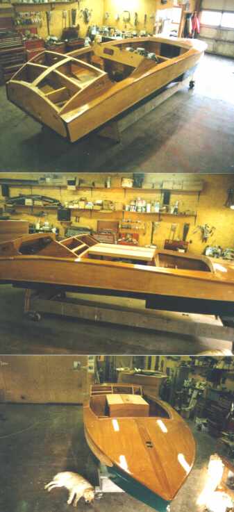
At present, the construction
is nearing it's final stages of sanding and varnishing, and then sanding
and varnishing some more. Then there will be the launching and testing.
I have been working toward that day for a long time. I have tried to predict
all of the problems which might possibly arise, but my engineering experience
says there will be some surpr i ses. We wait for the launch date with great
anticipation.
Click
here to return to the FLC's main page